VCO
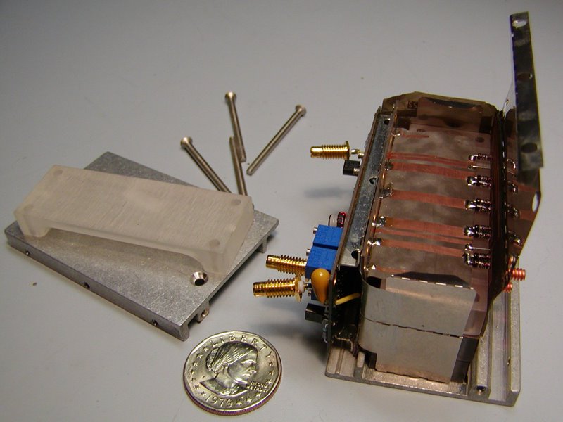
VCO Diodes must be between -3 to +3
Example: +2, +1, 0 = +3
'A' slot always has largest value diode
Prefabbing boards - Done training
After prefab test board with multimeter
-Hold red probe to bottom and touch each perforated square on top with black probe
-On top touch each row red probe behind one square of black probe. Looking for bridges. If multimeter sounds short to ground.
-After test visually inspect boards for any solder bridging or damage.
-New fixture for folding boards. Mickey Mouses toward you (diode side) board number always faces up. Start fold with fingers, then use fixture to get good crease. Fold membrane to cover traces by board number. Next, fold in to diode side. Leave diode side up.
-Load diodes. 'A' slot first (largest value) polarity stripe down into fixture. Smallest value goes into the left hole of each lettered pair of holes. The remaining value goes into the left hole of each lettered pair of holes. The remaining value (next largest) goes into the right hole of lettered pairs. POLARITY STRIPE DOWN.
-'A' slot has 122 board on fixture. Open membrane over traces before loading onto fixture. 118 board goes on the other side of fixture. Close fixture. Do not overtighten. Just finger snug.
-Load connectors into end of traces (membrane end) with hooked part of connectors facing up. Clamp into fixture snug.
-Load 3 bare wires. See doc for location.
-Begin soldering. Hold bare wires in until solder cools. Use fine solder wire. Do diodes, the connectors last.
-Clean all boards with acid brush and Acetone. Then inspect. Q-tip and Acetone inside of board. Double check polarity on diodes.
-Trim 3 bare wires even with diodes, then close clip diodes and connector leads.
-Clean fixtures with big brush and Acetone when done with soldering and inspection of boards.
-Fixture 158679 shown in doc with board facing you, use it facing away.
-Prefab steel board by folding in half and roll flat.
-Inspect plastic blocks for good threads and tuning holes. No cracks or bad threads for tuning slugs. Load 118 board first.
-Steel board fold one open end like airplane and load into fixture on top of 118 board. Fold little flaps back into center of steel board.
-Load 122 board into fixture on top of steel board. Close fixture.
-Nylon screws in counter sunk holes of plastic block.
-Flip fixture so diode leads are facing up.
-Load threaded studs with nut 1/4in. on side with deep allen socket up. Studs go into plastic blocks. Top row first.
-Load aluminum board with shiny half of cut outs facing up. Now load remaining three studs. Center board and tighten nuts by alternating.
-Trim fabric membrane on 117 board. See doc. Use small ruler for straightedge while trimming.
-Fig.1 after cut fold over to topside.
-Use big tip for soldering large flap of 117 board to 304 board. Use Q-tips to keep flap straight while solder cools.
-Use small tip to solder underside of traces. Seq. 17 clean with large brush and Acteone on sides, then little brush on top. Then Q-tip and Acetone on inside and top again. CLEAN FIXTURE.
-When soldering diodes, point leads in toward copper pads.
-Cut nylon tip almost all the way down to circuit side of 584 board. Check toroid wires. Inspect board for bridging and long leads.
-Add surface mount part 0160-5971 to 584 board. Before sequence 28.
-Solder sockets on circuit side of board with fine solder. Tack side rails in 3 places, then solder whole rail with fixture lifted.
-Solder tab last. Seq. 29.
posted by factory_peasant at 9:51 PM
![]()


1 Comments:
for Mike F.
you have the test procedure, you have scrap VCOs. use this in conjunction with the documentation. these are my original notes. revive your 62A to it's former glory...
good luck, brother.
Post a Comment
<< Home